
CAD Modeling for Hard-Surface Assets
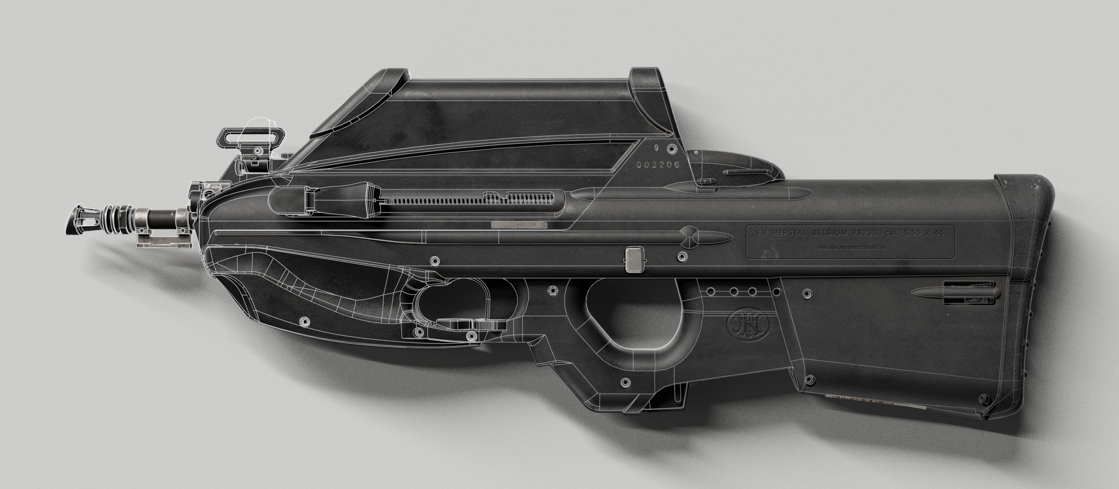
Most manufactured objects were designed in CAD before they existed physically. To recreate them accurately, work as close as possible to the environment in which they were originally designed. CAD helps the artist think in terms of construction logic, not just shape.
Once the reference base is collected, production can begin. In this section, we focus on hard-surface assets - objects created through design, engineering, manufacturing, and mechanical logic.
There is a simple rule that applies especially well to digital doubles and reverse-engineering workflows:
If you want to recreate an object accurately, work as close as possible to the environment in which it was originally designed.
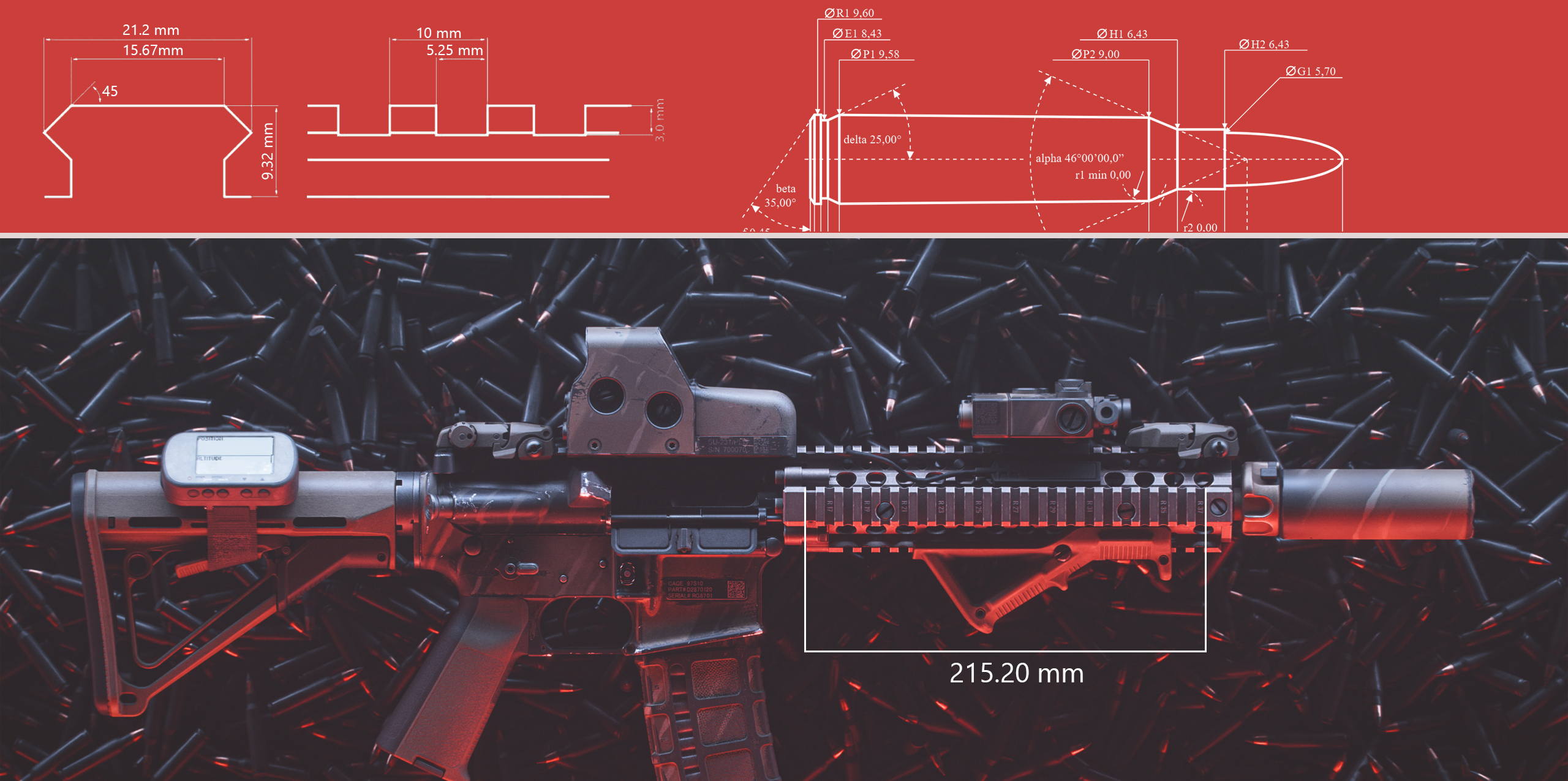
Many modern objects are first created in CAD. Weapon systems are a strong example: rail systems, screw types, barrel lengths, thread cuts, attachment points, pins, holes, receivers, and repeated engineering patterns are all metric, standardized, or mechanically constrained.
When an artist becomes comfortable working in CAD, they begin to understand why certain forms look the way they do. The shape of an object is rarely random - it is influenced by software limitations, manufacturing cost, available tooling, machining logic, assembly requirements, and functional constraints.
Why CAD Is Useful for Game Assets
Spline/NURBS geometry can be tessellated dynamically - the same model serves as a high-detail source for baking or a lightweight blockout for animation testing. Different departments get what they need without separate models.
One of the strongest benefits of CAD modeling is the ability to work with spline-based or NURBS-style geometry that can be tessellated dynamically.
This gives the production team flexibility. The same CAD model can be converted into a highly detailed mesh for high-poly work, or into a lighter version for early blockouts, animation testing, and in-engine validation.
This is especially useful in game production because different departments need different levels of detail at different stages:
- Animators may need an early low-detail blockout
- Designers may need a test asset inside the engine
- Artists need a high-detail source for baking
CAD allows the team to move faster during these early stages while still keeping proportions and mechanical relationships accurate.
The Main Challenges of CAD
Three challenges: (1) a different modeling mindset - operations and constraints instead of vertex pushing, (2) separate software and pipeline overhead (Plasticity, Fusion 360, SolidWorks), (3) weak at organic shapes and game-ready topology. CAD is a specialized tool, not a replacement for polygonal modeling.
1. A Different Modeling Mindset
CAD requires a different way of thinking. In polygonal modeling, artists move vertices, edges, and faces directly. In CAD, the workflow is based on operations: sketches, constraints, bevels, cuts, extrusions, booleans, fillets, chamfers, and parametric relationships.
It is not shaping a mesh by hand - it’s building an object through a sequence of logical construction steps. For many artists, this requires a complete mental shift.
2. Separate Software and Pipeline Overhead
CAD usually requires dedicated software such as Plasticity, Fusion 360, SolidWorks, or similar tools. This creates additional production overhead: licenses, software maintenance, export settings, file conversion, and data exchange between CAD and the main DCC package.
Some plugins allow NURBS or spline-based workflows inside traditional modeling software, but they are often less stable or more limited than dedicated CAD applications.
3. Software Limitations
For CAD, the main limitations are organic shapes, stylized forms, heavy scene performance, and the lack of flexible tools for simplified game-ready topology.
CAD is excellent for precision, mechanical parts, and clean industrial forms. It is less comfortable when the asset requires organic sculpting, expressive shape language, or fast artistic deformation.
CAD should not be treated as a replacement for polygonal modeling. It is a specialized tool that becomes extremely valuable when used for the right type of asset.
Modeling Process
Blockout first - correct scale, proportions, silhouette, moving parts. Then layer detail: large forms → medium forms → bevels, cuts, screws, panel breaks. Over time, artists notice recurring patterns: repeated radii, consistent distances, standard angles.
The CAD modeling process can be described as moving from primary blockout to layered detail.
First, we establish the blockout. At this stage, the goal is to define the correct scale, proportions, silhouette, and placement of the main functional elements. Moving parts and mechanical systems should be blocked out early, because they affect animation, interaction, and technical validation.
After that, detail is added layer by layer. The artist gradually moves from large forms to medium forms, and finally to small details: bevels, cuts, holes, screws, panel breaks, attachment points, stamped elements, and surface transitions.
One of the most valuable things CAD teaches is how to work with numbers. Over time, artists begin to notice patterns in real objects: repeated radii, consistent distances between holes, similar bevel widths, standard angles, symmetrical offsets, and recurring construction logic.
This understanding does not appear after one model. It develops gradually, after working through dozens of assets and comparing them against real-world references.
Working With Standards and Drawings
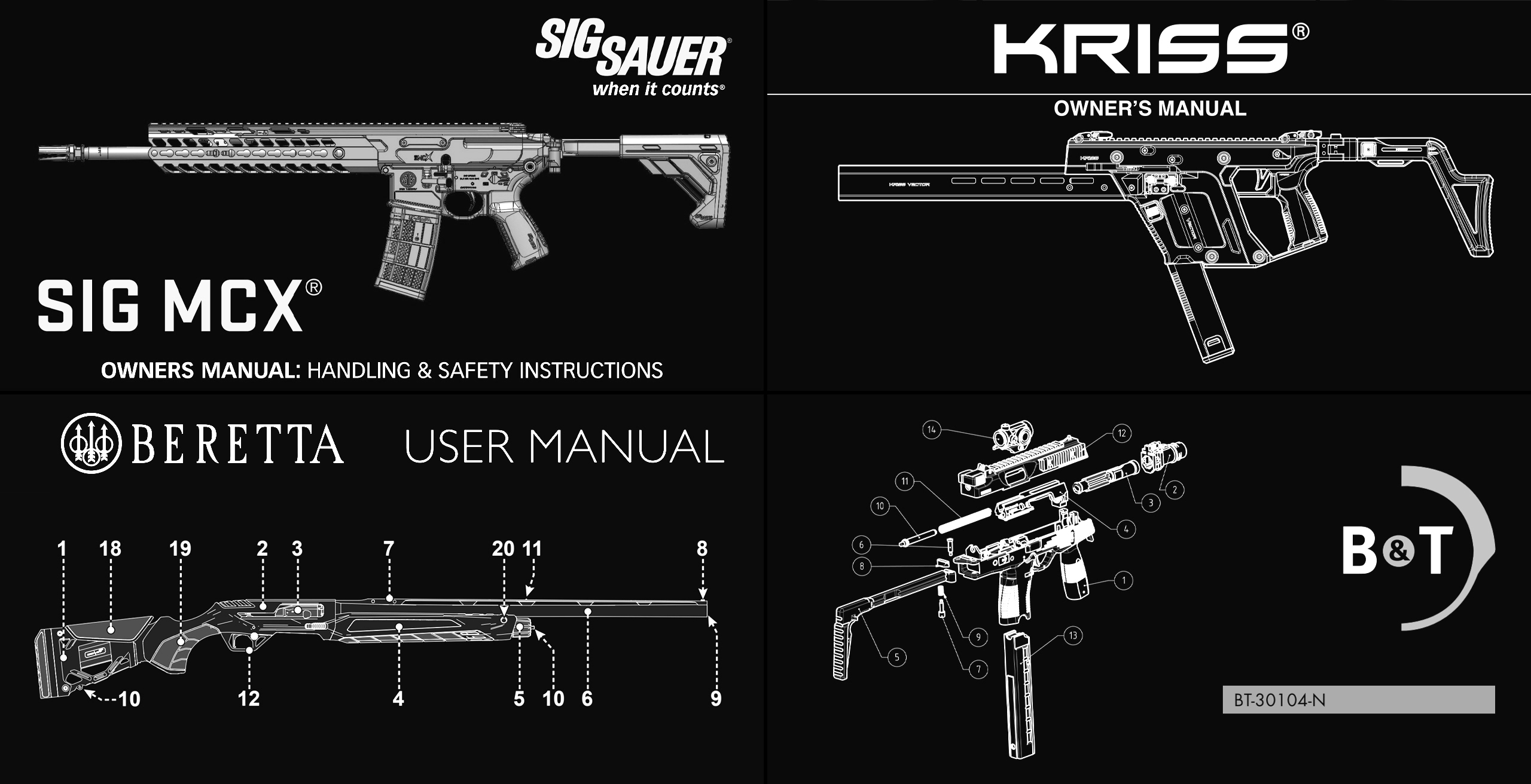
Whenever possible, it is important to search for drawings, technical documentation, and standardized dimensions. Many mechanical systems follow known standards.
If the artist can identify one reliable measurement in the reference, it becomes much easier to scale the entire object correctly in 3D space. For example, a standard Picatinny rail can serve as a starting point for bringing an object into compliance with real-world scale. Once that anchor is established, media references become much more useful because they can be interpreted through a measurable framework rather than by eye alone.